Here's the latest progress. It seems to be pretty much fully functional, both trigger mechanisms are wired into the single pull brake handle. The handle itself is a piece of 22.5 mm tubing that my bike mechanic friend says is used throughout the bike world for everything from handle bars to seat tubes, etc. The nice thing is that it's only a few thou larger than the .875 holes I had drilled, and so presses right on in to one of those standard bearing pocket holes. I fired up the metal lathe and made a couple of custom washers so I could run a piece of threaded rod right through the tube and screw it right on the handle bracket with a nut on each side. One of the washers fits in the bearing pocket hole, you can see it just as a steel disk from this side, while the other is a stepped washer to fit inside the tube on the far end of the handle:
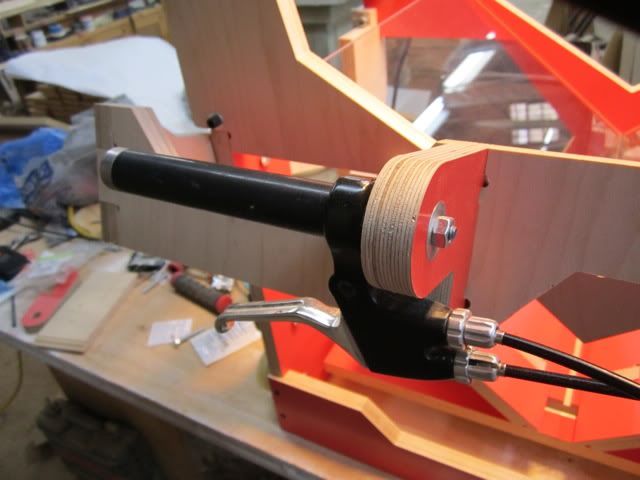
The cables came from a wonderful "bike tune up kit" that Gary or someone found at Walmart for a few bucks. I also couldn't resist a red and black handlebar grip that will make all this look like a Schwinn. The bike mechanic says when you're ready to put a plastic handlebar grip on a section of tubing for good, coat the metal tube with lady's hairspray. It acts as a lubricant for a few minutes and then sets up good. I knew that stuff had to be useful for something...
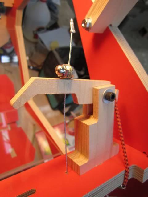
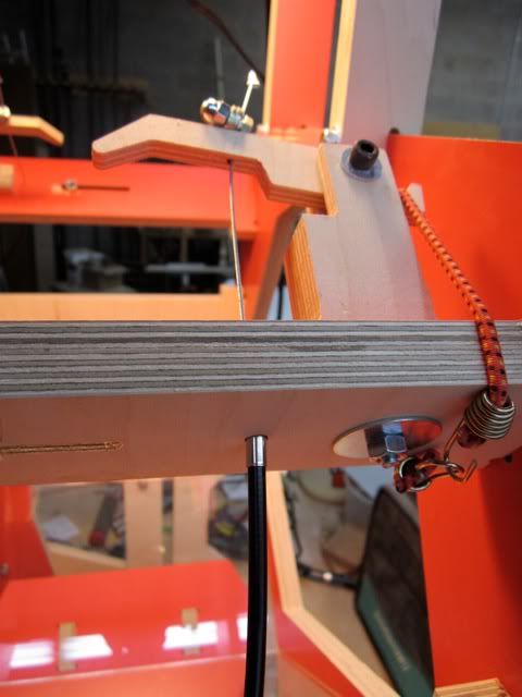
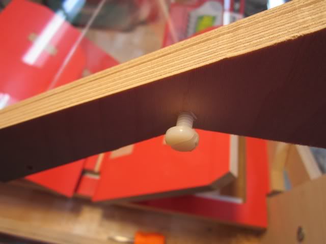
The camera trigger mechanisms are variations of the ones Gary came up with, but I cut them down a bit. I'm using these cool mini shockcords instead of elastic bands, they provide a good solid pull so the brake lever returns immediately after tripping the two camera shutters. I opted to screw in a stud from underneath each trigger housing, this fits through an oversize hole in the crossember, and into a large fender washer to allow lots of adjustment. It also seemed best to me to use the cross member as a housing cable stop, then drill the finger for the cable, and capture the cable with one of those old bicycle center pull brake nuts. It's basically just a bolt with a hole drilled in it for the cable. Lots of adjustment possible here. This will (hopefully!) all make more sense if you'll have a look at these pictures:
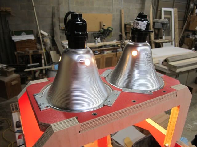
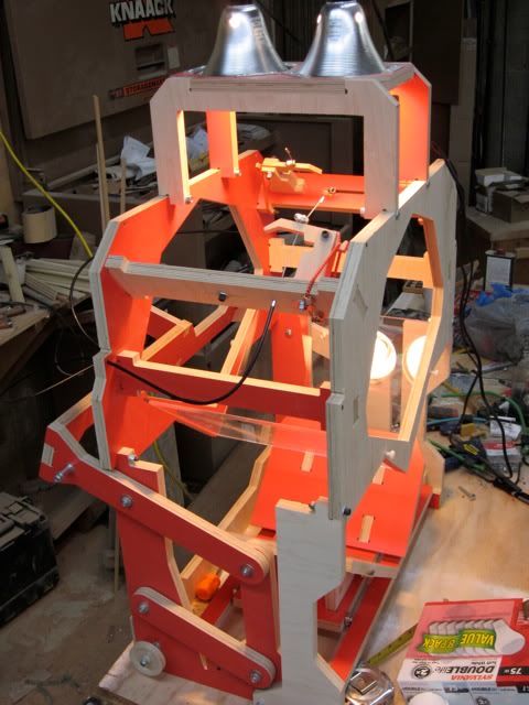
As also suggested by Gary before he headed off for points unknown, I used these two work lights from Lowes. They're reasonably cheap and quite bright:
The plexiglass platens slid in quite well, and I tapped a couple 1/4 X 20 holes for a couple nylon bolts to hold the platens steady and prevent them from sliding out. This works o.k., but it's easy to screw them in too far, in which case the main frame of the scanner separates and the platens simply fall out. I'm thinking I'll notch the platens in a couple places and use the screws to hold them in position that way. I wonder how easy it is to notch glass? Have to ask the glass people:
So here's the overall appearance at this point. The pulleys for the shock cords came from a couple of cheap clothes line pulleys, Lowes. They also sell 1/4 X 20 connecting nuts that make dandy pulley stand offs. I just bought a second camera this afternoon. I'm using two cheap point and shoots from Canon. The 14.1 megapixel A2200 is on sale this week at Best Buy for about $80, and that seemed like a reasonable choice. You don't see it in the photo here because I'm using it to take the picture. Should have put the other camera in for the photo but forgot. Sorry.
Tomorrow I'll take it all apart, sand the parts a bit, and shoot them flat black before reassembly. Then on to the software, about which I know very little.
cheers, Charles Morrill
Red shift...
Moderator: peterZ
Re: Red shift...
I am absolutely jealous of you
Re: Red shift...
Looks fantastic, equally jealous.
Do you have final measurements for your glass? I have no tools so I've asked the shop that is cutting the parts to assemble the frames for me, and I'd like to provide them with all the hardware and glass in advance of cutting - so obviously, your measurements would be invaluable.
- rob
- Posts: 773
- Joined: 03 Jun 2009, 13:50
- E-book readers owned: iRex iLiad, Kindle 2
- Number of books owned: 4000
- Country: United States
- Location: Maryland, United States
- Contact:
Re: Red shift...
That is a really, really good build! Now... have you tried turning the top part upside-down?
The Singularity is Near. ~ http://halfbakedmaker.org ~ Follow me as I build the world's first all-mechanical steam-powered computer.
-
- Posts: 56
- Joined: 17 Apr 2011, 21:20
- Number of books owned: 0
- Location: Charlottesville, Virginia
Re: Red shift...
Thanks everyone.
No, haven't tried turning the top section upside down yet. I was thinking I would probably make some sort of stand for it in this case as the lights at the top rather throw a wrinkle into paperback mode conversion...
My final platen sizes are two at 1/4 X 10 3/4 X 13 3/8ths. I'd originally thought 10 1/2 would be fine for length but bumped them up to 10 3/4 at the last minute. Probably doesn't make a whole lot of difference...
Regards, Charles
Re: Red shift...
Looks great! Do you think your shock cord solution for the trigger will work with the original cutouts GaryK made for the trigger? What is the length of the shock cords you used?
-
- Posts: 56
- Joined: 17 Apr 2011, 21:20
- Number of books owned: 0
- Location: Charlottesville, Virginia
Re: Red shift...
Should work with Gary's original design. Mine use the same outline as his, I just made my housing and trigger "finger" thinner because I wanted to. If my "fingers" prove too fragile in use, I'll press one of them into plastic modeling clay, remove, and use the impression to cast stronger trigger fingers in epoxy. All sorts of tricks you can accomplish like that using clay, auto-body filler and epoxy.
The triggering mechanisms, pulleys, and such also might be good candidates for addiditive machining techniques using a rep rap or makerbot.
Will check on shock cord length...
Cheers, Charles
The triggering mechanisms, pulleys, and such also might be good candidates for addiditive machining techniques using a rep rap or makerbot.
Will check on shock cord length...
Cheers, Charles
- daniel_reetz
- Posts: 2812
- Joined: 03 Jun 2009, 13:56
- E-book readers owned: Used to have a PRS-500
- Number of books owned: 600
- Country: United States
- Contact:
Re: Red shift...
Just wanted to throw my congratulations and admiration on the pile here, Charles. This is exquisite. I am jealous that your build is this much further advanced from my own.
-
- Posts: 56
- Joined: 17 Apr 2011, 21:20
- Number of books owned: 0
- Location: Charlottesville, Virginia
Re: Red shift...
Thanks Daniel. It looks good because you've done a terrific design.
Ateeq, those small shock cords are about a quarter inch thick by ten inches long. Lowes had a shock cord assortment for sale in a plastic container. Most of the cords seem a bit too strong but these were just perfect.
Charles
Ateeq, those small shock cords are about a quarter inch thick by ten inches long. Lowes had a shock cord assortment for sale in a plastic container. Most of the cords seem a bit too strong but these were just perfect.
Charles